|
|
| Enabler Test Specification (Conformance) for Smart City |
| Draft Version: 1.0 - 2025-04-16 |
| Open Mobile Alliance |
| uCIFI-OMA-ETS-Conformance-Smart-City-V1_0-20250416-D |
| Dev: 14 Jan 2026 16:09:00 rev: 656f03f |
|
|
| Enabler Test Specification (Conformance) for Smart City |
| Draft Version: 1.0 - 2025-04-16 |
| Open Mobile Alliance |
| uCIFI-OMA-ETS-Conformance-Smart-City-V1_0-20250416-D |
| Dev: 14 Jan 2026 16:09:00 rev: 656f03f |
Use of this document is subject to all of the terms and conditions of the Use Agreement located at https://www.omaspecworks.org/about/policies-and-terms-of-use/.
Unless this document is clearly designated as an approved specification, this document is a work in process, is not an approved Open Mobile Alliance™ specification, and is subject to revision or removal without notice.
You may use this document or any part of the document for internal or educational purposes only, provided you do not modify, edit or take out of context the information in this document in any manner. Information contained in this document may be used, at your sole risk, for any purposes. You may not use this document in any other manner without the prior written permission of the Open Mobile Alliance. The Open Mobile Alliance authorizes you to copy this document, provided that you retain all copyright and other proprietary notices contained in the original materials on any copies of the materials and that you comply strictly with these terms. This copyright permission does not constitute an endorsement of the products or services. The Open Mobile Alliance assumes no responsibility for errors or omissions in this document.
Each Open Mobile Alliance member has agreed to use reasonable endeavors to inform the Open Mobile Alliance in a timely manner of Essential IPR as it becomes aware that the Essential IPR is related to the prepared or published specification.
However, the members do not have an obligation to conduct IPR searches. The declared Essential IPR is publicly available to members and non-members of the Open Mobile Alliance and may be found on the “OMA IPR Declarations” list at https://www.omaspecworks.org/about/intellectual-property-rights/. The Open Mobile Alliance has not conducted an independent IPR review of this document and the information contained herein, and makes no representations or warranties regarding third party IPR, including without limitation patents, copyrights or trade secret rights. This document may contain inventions for which you must obtain licenses from third parties before making, using or selling the inventions. Defined terms above are set forth in the schedule to the Open Mobile Alliance Application Form.
NO REPRESENTATIONS OR WARRANTIES (WHETHER EXPRESS OR IMPLIED) ARE MADE BY THE OPEN MOBILE ALLIANCE OR ANY OPEN MOBILE ALLIANCE MEMBER OR ITS AFFILIATES REGARDING ANY OF THE IPR’S REPRESENTED ON THE “OMA IPR DECLARATIONS” LIST, INCLUDING, BUT NOT LIMITED TO THE ACCURACY, COMPLETENESS, VALIDITY OR RELEVANCE OF THE INFORMATION OR WHETHER OR NOT SUCH RIGHTS ARE ESSENTIAL OR NON-ESSENTIAL.
THE OPEN MOBILE ALLIANCE IS NOT LIABLE FOR AND HEREBY DISCLAIMS ANY DIRECT, INDIRECT, PUNITIVE, SPECIAL, INCIDENTAL, CONSEQUENTIAL, OR EXEMPLARY DAMAGES ARISING OUT OF OR IN CONNECTION WITH THE USE OF DOCUMENTS AND THE INFORMATION CONTAINED IN THE DOCUMENTS.
THIS DOCUMENT IS PROVIDED ON AN "AS IS" "AS AVAILABLE" AND "WITH ALL FAULTS" BASIS.
Copyright 2025 Open Mobile Alliance.
Used with the permission of the Open Mobile Alliance under the terms set forth above.
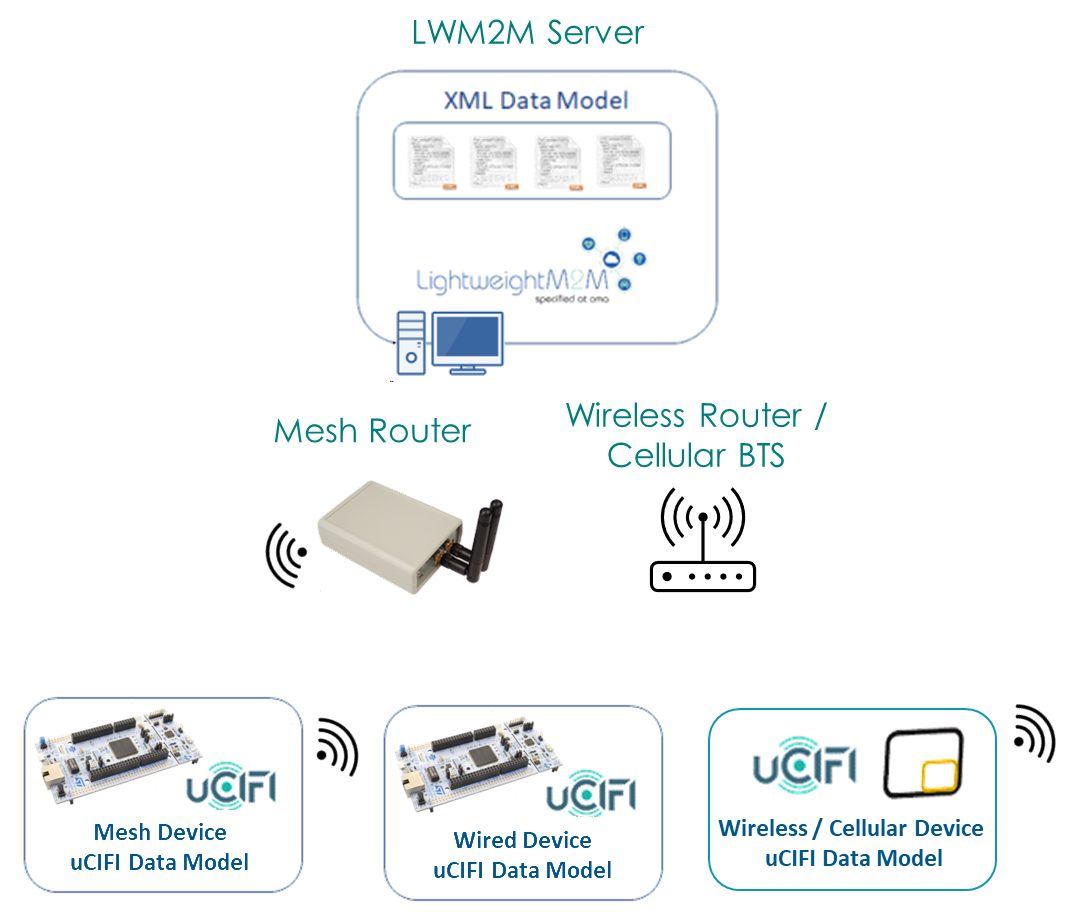
The uCIFI data model shall be implemented by Smart City device suppliers to run on constrained IoT networks such as NB-IoT, 6LowPAN, Wi-SUN and other generic TCP/IP networks that could support LwM2M over IPv4 and/or IPv6.
To ensure interoperability among devices implementing the uCIFI data model and help end-customers understand which device is compatible with the uCIFI data model, the Conformance Process has been defined.
| [RFC2119] | "Key words for use in RFCs to Indicate Requirement Levels", S. Bradner, March 1997, URL:http://www.ietf.org/rfc/rfc2119.txt |
| [RFC4234] | "Augmented BNF for Syntax Specifications: ABNF", D. Crocker, Ed., P. Overell, October 2005, URL:http://www.ietf.org/rfc/rfc4234.txt |
| [OMADICT] | "Dictionary for OMA Specifications", Version x.y, Open Mobile Alliance™, OMA-ORG-Dictionary-Vx_y, URL:http://www.openmobilealliance.org/ |
The key words "MUST", "MUST NOT", "REQUIRED", "SHALL", "SHALL NOT", "SHOULD", "SHOULD NOT", "RECOMMENDED", "MAY", and "OPTIONAL" in this document are to be interpreted as described in [RFC2119].
All sections and appendixes, except "Scope" and "Introduction", are normative, unless they are explicitly indicated to be informative.
| LWM2M Bootstrap Server Account | LWM2M Security Object Instance with Bootstrap Server Resource true |
| LWM2M Server Account | LWM2M Security Object Instance with Bootstrap Server Resource false and associated LWM2M Server Object Instance |
Kindly consult [OMADICT] for more definitions used in this document.
| CMS | Central Management System |
| D2D | Device To Device |
| DUT | Device Under Test |
| GW | Gateway |
| OMA | Open Mobile Alliance |
The objective of this document is to describe the overall uCIFI Conformance Process, including the uCIFI Conformance Tool.
First version of the document
Supported targets may include
The aim of uCIFI is to provide end-to-end interoperability. Implementations can fit on any standard IPv4 or IPv6 network: Cellular (NB-IoT, LTEM, xG), Wi-SUN, 6LowPAN, Ethernet or Wi-Fi.
uCIFI Data Model is currently modelled using OMA LwM2M objects and resources. For this reason a LwM2M client has to be provided within the implementation being tested. The certifications is performed relying on the Device Management and Information Reporting capabilities defined by the LwM2M standard.
The following LwM2M functionalities should be supported by the client:
From LwM2M 1.0
Bootstrap interface (optional)
Client Registration Interface
Device Management and Service Enablement Interface
Information Reporting Interface
Security (optional)
Data Formats
Plain Text
TLV
JSON (optional)
Additions from LwM2M 1.1
Device Management and Service Enablement Interface
Read composite (optional)
Write composite (optional)
Information Reporting Interface
Send operation handling (optional)
Security (optional)
TLS-Based Security (to be confirmed)
OSCORE (optional)
Data Formats
CBOR
SenML-JSON (optional)
SenML-CBOR
The uCIFI Conformance Software shall provide screens to record information about the candidate product, including:
Identity card of the candidate product:
Product Name
Endpoint Name
Unique Identifier (GTIN, IMEI, EAN) - retrieved automatically from Device Object 3
FW / SW Version (retrieved automatically from Device Object 3)
LwM2M Client Version (retrieved automatically from Registration)
Conformance Profile (Energy, Smart Streetlight, Environmental Monitoring, Smart Waste, Water Metering, Water Distribution Network, Public Safety, Parking, Traffic & Mobility)
Supported networks: See 1.5. Implementation requirements
Previous uCIFI Conformance: in case a previous version of the candidate product already received a uCIFI Conformance, the user shall enter the submission identifier corresponding to that previous certification.
Declaration of Product Feature List: the uCIFI Conformance Software tests only the LwM2M and uCIFI features that are implemented in the candidate product. This can be managed using an approach similar to PICS (Protocol Implementation Conformance Statement)
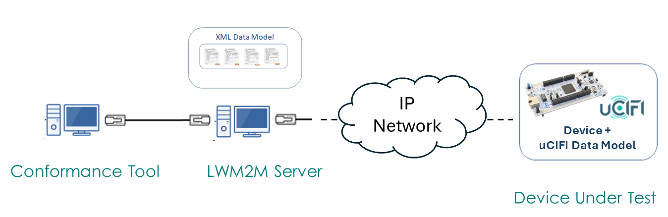
It is user responsibility to properly connect the DUT with the correct LwM2M Server (either locally or on cloud)
Each test case is specified with a unique name, directly derived from the Test Plan.
For example,
test_uCIFI_3_1_verify_u_i_p_metering
test_uCIFI_5_2_manual_switching_on_timestamp
Based on the profile selection, a number of mandatory test cases will be automatically selected.
For example, selecting Smart Streetlight profile would automatically select
To simplify the test identification, various profiles have been created under profiles folder
The user is then free to declare support for optional capabilities, thus including additional tests in the execution list.
The tests being executed have a direct correlation with what is declared (or required) to be supported in the Conformance Statement (see later).
Test case execution should then be automatically performed, without any user interaction, except for starting them
Tests execution may be requested to halt or continue in case of a failure and tests can be re-executed in case of failure.
Nevertheless, in order to assess the compliance, all mandatory tests shall pass.
Various options to execute the tests can be accounted.
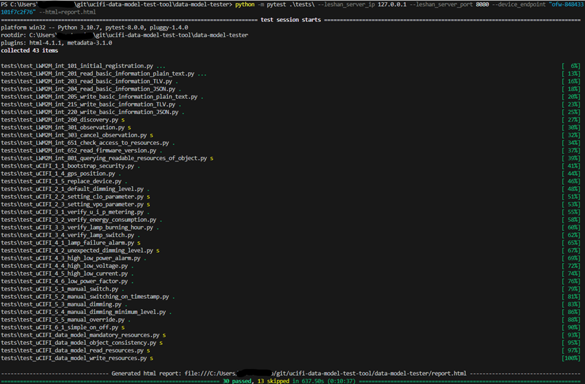
Tests can be easily invoked from command line by selecting the aforementioned profiles
pytest @profiles/generic_mandatory.txt --leshan_server_ip 127.0.0.1 --leshan_server_port 8080 --device_endpoint dut_name --html=reports/generic_mandatory.html

pytest @profiles/generic_optional.txt --leshan_server_ip 127.0.0.1 --leshan_server_port 8080 --device_endpoint dut_name --html=reports/generic_optional.html

pytest @profiles/smart_lighting_mandatory.txt --leshan_server_ip 127.0.0.1 --leshan_server_port 8080 --device_endpoint dut_name --html=reports/smart_lighting_mandatory.html

pytest @profiles/smart_lighting_optional.txt --leshan_server_ip 127.0.0.1 --leshan_server_port 8080 --device_endpoint dut_name --html=reports/smart_lighting_optional.html
User may be able to follow the execution in real-time or get notified later on, being provided with the result.
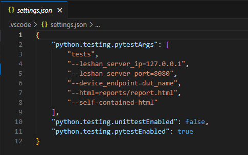
Visual Studio Code (VS Code) could be also used to execute test cases, providing a simplified interface to pytest
It can also be considered the preferred approach to debug the test executions or when developing new tests
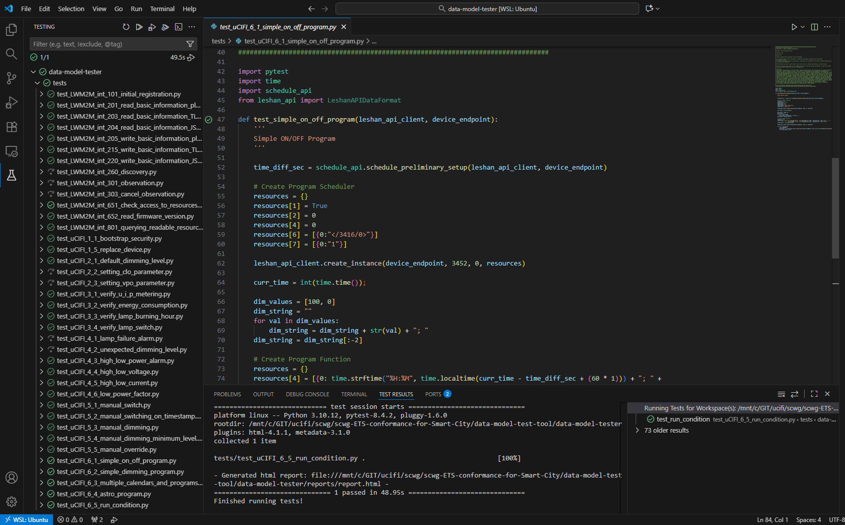
Detailed instructions can be found on the official website https://code.visualstudio.com/docs/python/testing
A JSON settings file is already included into the test folder and should allow for easy customization
The report should contain evidence about test execution, including failures, that may help the user to understand what need to be addressed (e.g. dry run, preliminary tests)
The generated report can be then zipped and sent to the Smart City Working Group for review.
[!NOTE]
The report archive should ideally contain the following content:
one or more reports in HTML format
the
assetsfolder (needed to keep proper formatting)the
conftest.pyto clearly state the configuration parameters and the versioningnetwork captures can be optionally included (such as Wireshark traces)
The user shall not alter the HTML report in any way before submission.
In addition to the report that is automatically generated, it may be required to manually fill an online survey as well (e.g. SurveyMonkey).
In this case coherent results should be indicated.
The following rules should be adopted to provide an acceptance criteria:
Products that passed the Conformance tests can be publicly listed on OMA Web Site together with the associated Conformance Statement.
To evaluate the conformance of a particular implementation to the uCIFI Data Model, it is necessary to have a statement of which capabilities and options have been implemented for a given implementation.
Such a statement is called Data Model Implementation Conformance Statement.
The implementer is asked to fill each row in the last column (labelled Implemented), specifying which requirement is satisfied or not.
In order to guarantee a minimum level of interoperability, some capabilities are considered mandatory and must be supported for a given use case. Other capabilities, instead, are considered optional and may be supported or not.
It is paramount that mandatory features must be implemented to pass the Conformance Test.
Each requirement is tested by one or more test cases. Tests will be then selected based on the implemented features . To comply with a requirement, all the associated tests should pass.
Each Feature mentioned in the Conformance Statement is associated with a mnemonic code (Item). To simplify readability, similar features are grouped together under the same high-level category.
| Implementation under test | |
|---|---|
| Name | |
| Version | |
| Software Version | |
| Hardware Version | |
| Operating System (optional) |
| Product Vendor | |
|---|---|
| Name | |
| Role | |
| Address | |
| Phone Number | |
| E-mail Address | |
| Additional Information |
| Contact Person | |
|---|---|
| Name | |
| Address | |
| Phone Number | |
| E-mail Address | |
| Additional Information |
The Generic Profile is mandatory and must be supported by all the various use cases.
| Item | Feature | Test cases | (M)andatory / (O)ptional |
Implemented (Y/N) |
|---|---|---|---|---|
| Device On-Boarding | ||||
| GEN-DOB-1 | Bootstrap and Security | GEN1.1 | O | |
| GEN-DOB-2 | Mandatory Objects and Resources | GEN1.2 | M |
| Item | Feature | Test cases | (M)andatory / (O)ptional |
Implemented (Y/N) |
|---|---|---|---|---|
| Device On-Boarding | ||||
| SL-DOB-1 | Inventory data | SL1.3 | O | |
| SL-DOB-2 | GPS position | SL1.4 | O | |
| SL-DOB-3 | Device replacement | SL1.5 | O | |
| Configuring | ||||
| SL-CONF1 | Default dimming level | SL2.1 | M | |
| SL-CONF2 | Constant Light Output | SL2.2 | O | |
| SL-CONF3 | Virtual Power Output | SL2.3 | O | |
| Monitoring | ||||
| SL-MON1 | Power measurements | SL3.1 | M | |
| SL-MON2 | Energy measurements | SL3.2 | M | |
| SL-MON3 | Lamp burning hours counter | SL3.3 | O | |
| SL-MON4 | Lamp switch on counter | SL3.4 | O | |
| SL-MON5 | Control Gear extra counters | SL3.5 | O | |
| Alarming | ||||
| SL-AL1 | Basic alarms | SL4.3 SL4.4 SL4.5 |
M | |
| SL-AL2 | Lamp failure alarms | SL4.1 | O | |
| SL-AL3 | Extra failures | SL4.2 SL4.6 SL4.7 |
O | |
| Controlling | ||||
| SL-CON1 | Lamp switching | SL5.1 SL5.2 |
M | |
| SL-CON2 | Lamp dimming | SL5.3 SL5.4 |
M | |
| SL-CON3 | Manual override | SL5.5 | O | |
| Programming | ||||
| SL-PROG1 | Basic Schedule Functionality | SL6.1 SL6.2 SL6.3 SL6.5 |
M | |
| SL-PROG2 | Astronomical Schedule functionality | SL6.4 | O | |
| SL-PROG3 | Dynamic control functionality (local) | SL6.6 | O | |
| SL-PROG4 | Dynamic control functionality (remote) | SL6.7 | O |
This section describes the uCIFI Data Model coverage in respect to the uCIFI test cases defined in the various profile specific documents.
uCIFI has specified a certain number of test cases to ensure compliancy with the uCIFI Data Model.
The following tables list for each resource in the data model the corresponding tests that check the specific functionality.
They can be used to better understand which part of the data model may require further review and testing,
| 3 | Device | Mandatory | Test |
|---|---|---|---|
| 0 | Manufacturer | Optional | |
| 1 | Model Number | Optional | |
| 2 | Serial Number | Optional | |
| 3 | Firmware Version | Optional | |
| 4 | Reboot | Mandatory | |
| 5 | Factory Reset | Optional | |
| 6 | Available Power Sources | Optional | |
| 7 | Power Source Voltage | Optional | |
| 8 | Power Source Current | Optional | |
| 9 | Battery Level | Optional | |
| 10 | Memory Free | Optional | |
| 11 | Error Code | Mandatory | |
| 12 | Reset Error Code | Optional | |
| 13 | Current Time | Optional | SL5.2 – Manual Switching with ON Timestamp SL6.3 - Multiple Calendars and Programs SL6.4 - Astro Program SL6.5 - Run Condition |
| 14 | UTC Offset | Optional | |
| 15 | Timezone | Optional | |
| 16 | Supported Binding and Modes | Mandatory | |
| 17 | Device Type | Optional | |
| 18 | Hardware Version | Optional | |
| 19 | Software Version | Optional | |
| 20 | Battery Status | Optional | |
| 21 | Memory Total | Optional | |
| 22 | ExtDevInfo | Optional |
| 3416 | Outdoor Lamp Controller | Mandatory | Test |
|---|---|---|---|
| 1 | Command | Mandatory | SL2.2 – Setting CLO Parameter SL2.3 – Setting VPO Parameter SL3.1 – Verify U, I, P Metering Values Consistency SL3.2 – Verify Energy Consumption When Lamp is Burning SL3.3 – Verify Lamp Burning Hour Counter When Lamp is Burning SL3.4 – Verify Lamp Switch On Counter SL4.2 – Unexpected Dimming Level SL4.3 – High / Low Power Alarm SL4.4 – High / Low Voltage SL4.5 – High / Low Current SL4.6 – Low Power Factor SL5.1 – Manual Switching SL5.2 – Manual Switching with ON Timestamp SL5.3 – Manual Dimming SL5.4 – Manual Dimming with Minimum Dimming Level SL5.5 – Manual Override SL6.1 - Simple ON/OFF Program SL6.2 - Simple Dimming Program SL6.3 - Multiple Calendars and Programs SL6.4 - Astro Program SL6.5 - Run Condition SL6.6 - Dynamic Control (Local) SL6.7 - Dynamic Control (Remote) |
| 2 | Command in action | Optional | SL5.1 – Manual Switching SL5.2 – Manual Switching with ON Timestamp SL5.3 – Manual Dimming SL5.4 – Manual Dimming with Minimum Dimming Level SL5.5 – Manual Override |
| 3 | Dimming level | Mandatory | SL2.1 – Setting Default Dimming Level SL2.2 – Setting CLO Parameter SL2.3 – Setting VPO Parameter SL4.2 – Unexpected Dimming Level SL4.5 – High / Low Current SL4.6 – Low Power Factor SL5.1 – Manual Switching SL5.3 – Manual Dimming SL5.4 – Manual Dimming with Minimum Dimming Level SL5.5 – Manual Override SL6.1 - Simple ON/OFF Program SL6.2 - Simple Dimming Program SL6.3 - Multiple Calendars and Programs SL6.4 - Astro Program SL6.5 - Run Condition SL6.6 - Dynamic Control (Local) SL6.7 - Dynamic Control (Remote) |
| 4 | Default dimming level | Optional | SL2.1 – Setting Default Dimming Level SL5.5 – Manual Override |
| 5 | Lamp failure | Optional | SL4.1 – Lamp Failure Alarms |
| 6 | Lamp failure reason | Optional | SL4.1 – Lamp Failure Alarms |
| 7 | Control gear failure | Optional | SL4.7 - Extra Failures |
| 8 | Control gear failure reason | Optional | SL4.7 - Extra Failures |
| 9 | Relay failure | Optional | SL4.7 - Extra Failures |
| 10 | Day burner | Optional | SL4.7 - Extra Failures |
| 11 | Cycling failure | Optional | SL4.7 - Extra Failures |
| 12 | Control gear communication failure | Optional | SL4.7 - Extra Failures |
| 13 | Optional | DEPRECATED | |
| 14 | Optional | DEPRECATED | |
| 15 | Lamp operating hours | Optional | SL1.5 – Replace a Device SL2.2 – Setting CLO Parameter SL3.3 – Verify Lamp Burning Hour Counter When Lamp is Burning |
| 16 | Lamp operating hours reset | Optional | SL1.5 – Replace a Device SL2.2 – Setting CLO Parameter |
| 17 | Lamp ON timestamp | Optional | SL5.2 – Manual Switching with ON Timestamp |
| 18 | Lamp switch counter | Optional | SL1.5 – Replace a Device SL3.4 – Verify Lamp Switch On Counter |
| 19 | Lamp switch counter reset | Optional | SL1.5 – Replace a Device SL3.4 – Verify Lamp Switch On Counter |
| 20 | Control gear start counter | Optional | SL3.5 - Control Gear extra counters |
| 21 | Control gear temperature | Optional | |
| 22 | Control gear thermal derating | Optional | SL3.5 - Control Gear extra counters |
| 23 | Control gear thermal derating counter | Optional | SL3.5 - Control Gear extra counters |
| 24 | Control gear thermal derating counter reset | Optional | SL3.5 - Control Gear extra counters |
| 25 | Control gear thermal shutdown | Optional | SL3.5 - Control Gear extra counters |
| 26 | Control gear thermal shutdown counter | Optional | SL3.5 - Control Gear extra counters |
| 27 | Control gear thermal shutdown counter reset | Optional | SL3.5 - Control Gear extra counters |
| 28 | Output port | Optional | |
| 29 | Standby mode | Optional | |
| 30 | Constant light output | Optional | SL2.2 – Setting CLO Parameter |
| 31 | Cleaning factor enabled | Optional | |
| 32 | Cleaning period | Optional | |
| 33 | Initial lamp cleaning factor | Optional | |
| 34 | Lamp cleaning date | Optional | |
| 35 | Control type | Optional | |
| 36 | Nominal Lamp wattage | Optional | |
| 37 | Minimum dimming level | Optional | SL5.4 – Manual Dimming with Minimum Dimming Level |
| 38 | Minimum lamp wattage | Optional | |
| 39 | Light colour temperature command | Optional | |
| 40 | Actual light colour temperature | Optional | |
| 41 | Virtual power output | Optional | SL2.3 – Setting VPO Parameter |
| 42 | Voltage at max dim level | Optional | |
| 43 | Voltage at min dim level | Optional | |
| 44 | Light source voltage | Optional | |
| 45 | Light source current | Optional | |
| 46 | Light source active power | Optional | |
| 47 | Light source active energy | Optional | |
| 48 | Maximum light source current | Optional | |
| 49 | Default fade time | Optional | |
| 50 | Manual override start time | Optional | |
| 51 | Manual override end time | Optional | |
| 52 | Manual override fade | Optional | |
| 53 | Manual override default duration | Optional | SL5.5 – Manual Override |
| 54 | Manual override active | Optional | SL5.5 – Manual Override |
| 55 | Default Light colour temperature | Optional | |
| 56 | Driver operating hours | Optional | |
| 57 | Driver operating hours reset | Optional | |
| 58 | Manufacturer GTIN | Optional | |
| 59 | Manufacturer Serial Number | Optional | |
| 60 | Firmware Version | Optional | |
| 61 | DALI Version | Optional | |
| 62 | Unit temperature | Optional | |
| 63 | Device capabilities | Optional | |
| 5518 | Timestamp | Optional | |
| 6050 | Fractional Timestamp | Optional | |
| 6042 | Measurement Quality Indicator | Optional | |
| 6049 | Measurement Quality Level | Optional |
| 3417 | Luminaire Asset | Mandatory | Test |
|---|---|---|---|
| 1 | Asset GTIN | Mandatory | SL1.3 – Read Inventory Data |
| 2 | Year of manufacture | Optional | |
| 3 | Week of manufacture | Optional | |
| 4 | Nominal light output | Optional | |
| 5 | Light distribution type | Optional | |
| 6 | Luminaire color | Optional | |
| 7 | Nominal input power | Optional | |
| 8 | Power at minimum dim level | Optional | |
| 9 | Nominal max AC mains voltage | Optional | |
| 10 | Nominal min AC mains voltage | Optional | |
| 11 | CRI | Optional | |
| 12 | CCT value | Optional | |
| 13 | Luminaire identification | Optional | |
| 14 | Luminaire identification number | Optional |
| 3418 | Electrical Monitor | Mandatory | Test |
|---|---|---|---|
| 1 | Supply voltage | Optional | SL3.1 – Verify U, I, P Metering Values Consistency |
| 2 | Supply current | Optional | SL3.1 – Verify U, I, P Metering Values Consistency SL4.5 – High / Low Current |
| 3 | Frequency | Optional | |
| 4 | Active power | Optional | SL2.3 – Setting VPO Parameter SL3.1 – Verify U, I, P Metering Values Consistency SL3.2 – Verify Energy Consumption When Lamp is Burning SL4.3 – High / Low Power Alarm |
| 5 | Power factor | Optional | SL3.1 – Verify U, I, P Metering Values Consistency SL4.6 – Low Power Factor |
| 6 | Cumulated active energy | Optional | SL1.5 – Replace a Device SL3.2 – Verify Energy Consumption When Lamp is Burning |
| 7 | Energy reset | Optional | SL1.5 – Replace a Device |
| 8 | Low power factor threshold | Optional | SL4.6 – Low Power Factor |
| 9 | Low power factor | Optional | SL4.6 – Low Power Factor |
| 10 | Low power threshold | Optional | SL4.3 – High / Low Power Alarm |
| 11 | Low power threshold at low dim level | Optional | |
| 12 | Low power | Optional | SL4.3 – High / Low Power Alarm |
| 13 | High power threshold | Optional | SL4.3 – High / Low Power Alarm |
| 14 | High power threshold at low dim level | Optional | |
| 15 | High power | Optional | SL4.3 – High / Low Power Alarm |
| 16 | Low current threshold | Optional | SL4.5 – High / Low Current |
| 17 | Low current | Optional | SL4.5 – High / Low Current |
| 18 | High current threshold | Optional | SL4.5 – High / Low Current |
| 19 | High current | Optional | SL4.5 – High / Low Current |
| 20 | Low voltage threshold | Optional | SL4.4 – High / Low Voltage |
| 21 | Low voltage | Optional | SL4.4 – High / Low Voltage |
| 22 | High voltage threshold | Optional | SL4.4 – High / Low Voltage |
| 23 | High voltage | Optional | SL4.4 – High / Low Voltage |
| 24 | Critical inrush threshold | Optional | |
| 25 | Critical inrush current | Optional | |
| 26 | Minimum inrush Current | Optional | |
| 27 | Maximum inrush Current | Optional | |
| 28 | Latest inrush Current | Optional | |
| 29 | Reactive power | Optional | |
| 30 | Reactive energy | Optional | |
| 31 | Low power threshold at custom dim level | Optional | |
| 32 | High power threshold at custom dim level | Optional | |
| 33 | Custom dim level min range | Optional | |
| 34 | Custom dim level max range | Optional | |
| 35 | Dimming level | Optional | |
| 5518 | Timestamp | Optional | |
| 6050 | Fractional Timestamp | Optional | |
| 6042 | Measurement Quality Indicator | Optional | |
| 6049 | Measurement Quality Level | Optional |
| 3452 | Program Scheduler | Mandatory | Test |
|---|---|---|---|
| 0 | Schedule Name | Optional | |
| 1 | State | Mandatory | SL6.1 - Simple ON/OFF Program SL6.2 - Simple Dimming Program SL6.3 - Multiple Calendars and Programs SL6.4 - Astro Program SL6.5 - Run Condition SL6.6 - Dynamic Control (Local) SL6.7 - Dynamic Control (Remote) |
| 2 | Priority | Mandatory | SL6.1 - Simple ON/OFF Program SL6.2 - Simple Dimming Program SL6.3 - Multiple Calendars and Programs SL6.4 - Astro Program SL6.5 - Run Condition SL6.6 - Dynamic Control (Local) SL6.7 - Dynamic Control (Remote) |
| 3 | Calendar Rules | Optional | |
| 4 | Program Function | Mandatory | SL6.1 - Simple ON/OFF Program SL6.2 - Simple Dimming Program SL6.3 - Multiple Calendars and Programs SL6.4 - Astro Program SL6.5 - Run Condition SL6.6 - Dynamic Control (Local) SL6.7 - Dynamic Control (Remote) |
| 5 | Input Sources | Optional | SL6.6 - Dynamic Control (Local) SL6.7 - Dynamic Control (Remote) |
| 6 | Output Instances | Mandatory | SL6.1 - Simple ON/OFF Program SL6.2 - Simple Dimming Program SL6.3 - Multiple Calendars and Programs SL6.4 - Astro Program SL6.5 - Run Condition SL6.6 - Dynamic Control (Local) SL6.7 - Dynamic Control (Remote) |
| 7 | Output Targets | Mandatory | SL6.1 - Simple ON/OFF Program SL6.2 - Simple Dimming Program SL6.3 - Multiple Calendars and Programs SL6.4 - Astro Program SL6.5 - Run Condition SL6.6 - Dynamic Control (Local) SL6.7 - Dynamic Control (Remote) |
| 8 | Compound Operation | Optional | |
| 9 | Off when inactive | Optional | SL6.5 - Run Condition |
| 3453 | Calendar Rule | Mandatory | Test |
|---|---|---|---|
| 0 | Calendar Name | Optional | |
| 1 | Calendar Type | Optional | |
| 2 | Start Date | Optional | SL6.3 - Multiple Calendars and Programs |
| 3 | End Date | Optional | SL6.3 - Multiple Calendars and Programs |
| 4 | Date Rule | Optional | SL6.3 - Multiple Calendars and Programs SL6.4 - Astro Program |
| 5 | Calendar Active | Optional |
| 3454 | Program Function | Mandatory | Test |
|---|---|---|---|
| 0 | Function Name | Optional | |
| 1 | Run Condition | Optional | SL6.5 - Run Condition |
| 3 | Output Filter | Optional | |
| 4 | Time Input Array | Mandatory | SL6.1 - Simple ON/OFF Program SL6.2 - Simple Dimming Program SL6.3 - Multiple Calendars and Programs SL6.4 - Astro Program SL6.5 - Run Condition |
| 5 | Time Output Array | Mandatory | SL6.1 - Simple ON/OFF Program SL6.2 - Simple Dimming Program SL6.3 - Multiple Calendars and Programs SL6.4 - Astro Program SL6.5 - Run Condition |
| 6 | Single Sensor Input Array | Optional | SL6.6 - Dynamic Control (Local) SL6.7 - Dynamic Control (Remote) |
| 7 | Multi Sensor Input Array | Optional | |
| 8 | Sensor Output Array | Optional | SL6.6 - Dynamic Control (Local) SL6.7 - Dynamic Control (Remote) |
| 9 | Output Filter for Time Output | Optional | |
| 10 | Output Filter for Sensor Output | Optional |
| 3457 | Program Manager | Mandatory | Test |
|---|---|---|---|
| 0 | Max number of Program Schedulers | Mandatory | |
| 1 | Current number of Program Schedulers | Mandatory | |
| 2 | Max number of Program Functions | Mandatory | |
| 3 | Current number of Program Functions | Mandatory | |
| 4 | Max number of Calendars | Mandatory | |
| 6 | Max number of Actuators | Mandatory | |
| 7 | Max number of Input Sources | Optional | |
| 8 | Max number of Dates in Calendar | Optional | |
| 9 | Max Flash Memory Allocated | Mandatory | |
| 10 | Flash Memory Free | Optional | |
| 11 | Error Conditions | Mandatory | |
| 12 | Clear errors | Optional | |
| 13 | Supported Capabilities | Optional | |
| 14 | Max Dynamic Memory Allocated | Optional | |
| 15 | Dynamic Memory Free | Optional | |
| 16 | Reset schedule objects | Optional | SL6.1 - Simple ON/OFF Program SL6.2 - Simple Dimming Program SL6.3 - Multiple Calendars and Programs SL6.4 - Astro Program SL6.5 - Run Condition SL6.6 - Dynamic Control (Local) SL6.7 - Dynamic Control (Remote) |
| 3459 | Distributed Sensor Group | Mandatory | Test |
|---|---|---|---|
| 0 | Group State | Optional | |
| 1 | Most recent group activity | Optional | |
| 2 | Most recent Sensor Notification | Optional | |
| 3 | Most recent Sensor Publisher ID | Optional | |
| 4 | Group Address | Optional | SL6.7 - Dynamic Control (Remote) |
| 5 | Group ID | Optional | |
| 6 | Shared Sensor information | Optional | |
| 7 | Quality of service | Optional | |
| 8 | Hop Limit | Optional | |
| 9 | Broadcast Criteria | Optional | |
| 10 | Min Broadcast Period | Optional | |
| 11 | Max Broadcast Period | Optional | |
| 12 | Publisher Step interval | Optional | SL6.7 - Dynamic Control (Remote) |
| 13 | Min Threshold | Optional | |
| 14 | Max Threshold | Optional | |
| 15 | Auto Clear Validity Time | Optional | |
| 16 | Auto Clear Default Value | Optional | |
| 17 | Data Fusion Operation | Optional | |
| 18 | Remote Sensors Dynamic Mapping | Optional | |
| 19 | Remote Sensors Implicit Mapping | Optional | |
| 20 | Local Sensor State URI | Optional | SL6.7 - Dynamic Control (Remote) |
| 21 | Local Sensor Publisher ID | Optional | SL6.7 - Dynamic Control (Remote) |
| 22 | Remote Sensor State URI | Optional | |
| 23 | Group Log | Optional | |
| 24 | Group Description | Optional |
| 3461 | Sensor Group Device Capabilities | Mandatory | Test |
|---|---|---|---|
| 1 | Remote Sensor Management capabilities | Optional | |
| 2 | Max number of explicit sensors | Optional | |
| 3 | Max number of implicit sensors | Optional | |
| 4 | Data Fusion Capabilities | Optional | |
| 5 | Reset DSG objects | Optional | SL6.7 - Dynamic Control (Remote) |
This section describes the uCIFI Test Plan that is used when certifying devices.
This document should cover the definition of test cases that are provided to ensure compliancy with the Data Model published by the uCIFI Alliance.
Test case definition is first done using a flow chart approach, in order to agree on the overall behaviour that has to be expected by Devices Under Test.
Then the test case is mapped into a separate file to be fed into an external tool that could perform automatic tests.
Tests may cover multiple use cases, from Smart Lighting to Smart Waste or more generic Sensor Networks and are divided into functional categories, similar for each use case:
Checking that, when the device connects to LwM2M, the protocol and data model is properly implemented, and the device will work as expected for outdoor lighting.
Checking that the device accepts and uses configuration parameters to work properly for outdoor lighting applications.
Checking that the device properly reads and reports electrical (voltage, current, power, energy) and other attributes (e.g. lamp burning hours, temperature, ambient light).
Checking that the device reports alarms to the LwM2M servers as required in outdoor lighting applications
Checking that the device implements various remote-control mechanisms as required in outdoor lighting applications.
Checking that the device accepts and properly runs control programs based on astronomical clocks, photocell or fixed time schedule and programs.
| Test Case | M/O | PyTest | Notes |
|---|---|---|---|
| 5.1.1. TEST CASE #GEN1.1 – Bootstrap and Security | O | Device shall be pre-commissioned accordingly. See discussion about commissioning | |
| 5.1.2. TEST CASE #GEN1.2 – Mandatory Objects & Resources Type | M | Checking proper format may not be trivial |
Test Case Prerequisites
DUT is connected to and active in the LwM2M server embedded in the Certification Tool
Supplier declares to support :
Outdoor Lamp Controller
Test Case Definition
graph LR
    A[Test Start] --> B[Check that the device is properly <br> connected to the LwM2M server]
    B --> C{Device is connected?}
    C --> |Yes| D["Check that the announced <br> security mechanism is in place <br> (mechanism to be defined)"]
    C --> |No| Fail[Test Failed]
    D --> E{Security is properly <br> implemented?}
    E --> |No| Fail
    E --> |Yes| Success[Test Success]
Test Case Prerequisites
Client tested device is connected to and active in the LwM2M server embedded in the Certification Tool
Supplier declares to support :
Outdoor Lamp Controller
Electrical Monitor
Test Case Definition
graph LR
    A[Test Start] --> B[For each attribute of each object <br> declared in the LwM2M server, <br> check the presence of each  <br> mandatory resource in the uCIFI <br> Data Model]
    B --> C{Each mandatory <br> resource is present?}
    C --> |No| Fail[Test Failed]
    C --> |Yes| D[For each attribute of each <br> object declared in the LwM2M <br> server, check the format of <br> each declared resource <br> compared to the uCIFI <br> Data Model]
    D --> E{Each resource <br> has the right <br> format?}
    E --> |No| Fail
    E --> |Yes| Success[Test Success]
| 3 | Device | Mandatory | Test |
|---|---|---|---|
| 0 | Manufacturer | Optional | |
| 1 | Model Number | Optional | |
| 2 | Serial Number | Optional | |
| 3 | Firmware Version | Optional | |
| 4 | Reboot | Mandatory | |
| 5 | Factory Reset | Optional | |
| 6 | Available Power Sources | Optional | |
| 7 | Power Source Voltage | Optional | |
| 8 | Power Source Current | Optional | |
| 9 | Battery Level | Optional | |
| 10 | Memory Free | Optional | |
| 11 | Error Code | Mandatory | |
| 12 | Reset Error Code | Optional | |
| 13 | Current Time | Optional | 5.2 – Manual Switching with ON Timestamp |
| 14 | UTC Offset | Optional | |
| 15 | Timezone | Optional | |
| 16 | Supported Binding and Modes | Mandatory | |
| 17 | Device Type | Optional | |
| 18 | Hardware Version | Optional | |
| 19 | Software Version | Optional | |
| 20 | Battery Status | Optional | |
| 21 | Memory Total | Optional | |
| 22 | ExtDevInfo | Optional |
This section describes the uCIFI Test Plan that is used when certifying devices.
This document should cover the definition of test cases that are provided to ensure compliancy with the Data Model published by the uCIFI Alliance.
Test case definition is first done using a flow chart approach, in order to agree on the overall behaviour that has to be expected by Devices Under Test.
Then the test case is mapped into a separate file to be fed into an external tool that could perform automatic tests.
Tests may cover multiple use cases, from Smart Lighting to Smart Waste or more generic Sensor Networks and are divided into functional categories, similar for each use case:
Checking that, when the device connects to LwM2M, the protocol and data model is properly implemented, and the device will work as expected for outdoor lighting.
Checking that the device accepts and uses configuration parameters to work properly for outdoor lighting applications.
Checking that the device properly reads and reports electrical (voltage, current, power, energy) and other attributes (e.g. lamp burning hours, temperature, ambient light).
Checking that the device reports alarms to the LwM2M servers as required in outdoor lighting applications
Checking that the device implements various remote-control mechanisms as required in outdoor lighting applications.
Checking that the device accepts and properly runs control programs based on astronomical clocks, photocell or fixed time schedule and programs.
Test Case Prerequisites
Client tested device is connected to and active in the LwM2M server embedded in the Certification Tool
Supplier declares to support :
Luminaire asset
Test Case Definition
graph LR
    A[Test Start] --> B[Check that the GTIN <br> is present and not null]
    B --> C{GTIN is present <br> and not null ?}
    C --> |No| Fail[Test Failed]
    C --> |Yes| D[For each declared attribute of <br> the Luminaire Asset object, <br> check that values are not null]
    D --> E{Values are <br> not null?}
    E --> |No| Fail
    E --> |Yes| Success[Test Success]
Test Case Prerequisites
Client tested device is connected to and active in the LwM2M server embedded in the Certification Tool
Supplier declares to support :
Location
Global Navigation Satellite System
Test Case Definition
graph LR
    A[Test Start] --> B["Read Latitude and Longitude from <br> Location (/6/) or GNSS (/3430/) object"]
    B --> C{"Are lat and <br> lon valid <br> (not null)?"}
    C --> |No| Fail[Test Failed]
    C --> |Yes| D[If the GNSS object is implemented, <br> make two reads of lat and lon <br> from the GNSS object within <br> 1 minute interval]
    D --> E{Are values and <br> timestamp <br> consistent?}
    E --> |No| Fail
    E --> |Yes| Success[Test Success]
Test Case Prerequisites
Client tested device is connected to and active in the LwM2M server embedded in the Certification Tool
Supplier declares to support :
Outdoor Lamp Controller
Electrical Monitor
Test Case Definition
graph LR
    A[Test Start] --> B[Read lamp operating hours, <br> lamp switch on counter and <br> cumulative energy value]
    B --> C{Are these values valid <br> and greater than zero?}
    C --> |No| Fail[Test Failed]
    C --> |Yes| D[Reset lamp operating hours, <br> lamp switch on counter and <br> cumulative energy value]
    D --> E{Are these values <br> now equal to zero?}
    E --> |No| Fail
    E --> |Yes| Success[Test Success]
Test Case Prerequisites
Client tested device is connected to and active in LwM2M servers embedded in the Certification Tool
Success of all generic test cases
Supplier declares to support:
Outdoor Lamp Controller
Test Case Definition
graph LR
    A[Test Start] --> B[* all schedules <br> shall have been <br> deleted in advance]
    B --> C["Set default dimming level <br> (/3416/0/4) to a random value <br> between 50 and 100"]
    C --> D[Wait a few <br> seconds]
    D --> E{Check that /3416/0/3 <br> is equal to /3416/0/4}
    E --> |No| Fail
    E --> |Yes| Success[Test Success]
Test Case Prerequisites
Client tested device is connected to and active in LwM2M servers embedded in the Certification Tool
Success of all generic test cases
Supplier declares to support :
Outdoor Lamp Controller
Test Case Definition
graph TD
A[Test Start] --> B[Ask user to provide a light point <br> controller with lamp operating <br> hours being significant]
B --> C{Check that lamp operating hours <br> /3416/0/15 >> 0}
C --> |No| Fail[Test Failed]
C --> |Yes| D[Set constant light output <br> /3416/0/30 to TRUE]
D --> E[Set command /3416/0/1 to 100]
E --> F{Check that dimming <br> level /3416/0/3 is <br> < command /3416/0/1}
F --> |No| Fail
F --> |Yes| G[Reset lamp operating hours <br>/3416/0/16]
G --> H{Check that dimming <br> level /3416/0/3 is <br> even smaller than <br> before}
H --> |No| Fail
H --> |Yes| Success[Test Success]
Test Case Prerequisites
Client tested device is connected to and active in LwM2M servers embedded in the Certification Tool
Success of all generic test cases
Supplier declares to support :
Outdoor Lamp Controller
Electrical Monitoring
Test Case Definition
graph LR
A[Test Start] --> B["Set Virtual Power Output <br> (/3416/0/41) to 100"]
B --> C["Set /3416/0/1 to 100"]
C --> D{"Check that <br> /3418/0/4 is >> 0 <br> Record it as <br> "max power""}
D --> |No| Fail[Test Failed]
D --> |Yes| E["Set Virtual Power Output <br> (/3416/0/41) to 80"]
E --> F{"Check that /3418/0/4 <br> is equal to 80% <br> of "max power""}
F --> |No| Fail
F --> |Yes| Success[Test Success]
Test Case Prerequisites
Client tested device is connected to and active in LwM2M servers embedded in the Certification Tool
Success of all generic test cases
Supplier declares to support :
Outdoor Lamp Controller
Electrical Monitoring
Test Case Definition
graph TD
A[Test Start] --> B[Set command <br> /3416/0/1 to 100]
B --> C[Delay / Max <br> Timeout = 2 mins]
C --> D{Read active power <br> 3418/0/4 and check <br> is >> 0}
D --> |No| Fail[Test Failed]
D --> |Yes| E[Read /3418/0/1, <br> /3418/0/2 and <br> /3418/0/5]
E --> F{Check that <br> supply voltage <br> x supply current <br> = active power}
F --> |No| Fail
F --> |Yes| G[Set command <br> /3416/0/1 to 30]
G --> H[Delay / Max <br> Timeout = 2 mins]
H --> I{Read /3418/0/5 <br> and verify that <br> is between 0.5 <br> and 1.0}
I --> |No| Fail
I --> |Yes| Success[Test Success]
Test Case Prerequisites
Client tested device is connected to and active in LwM2M servers embedded in the Certification Tool
Success of all generic test cases
Supplier declares to support :
Outdoor Lamp Controller
Electrical Monitoring
Test Case Definition
graph TD
A[Test Start] --> B["Read /3418/0/6 <br> and record it as <br> 'Initial energy'"]
B --> C["Set command <br> /3416/0/1 to 100"]
C --> D{"Check that active <br> power /3418/0/4 <br> is >> 0"}
D --> |No| Fail[Test Failed]
D --> |Yes| E["Read /3418/0/6. <br> Repeat until change <br> is observed. Max <br> 1 hour timeout"]
E --> F{"Check that 'initial energy' <br> + (active power * elapsed time) <br> = cumulated energy"}
F --> |No| Fail
F --> |Yes| Success[Test Success]
Test Case Prerequisites
Client tested device is connected to and active in LwM2M servers embedded in the Certification Tool
Success of all generic test cases
Supplier declares to support :
Outdoor Lamp Controller
</3416/0/1> Command
</3416/0/15> Lamp operating hours
Test Case Definition
graph TD
A[Test Start] --> B["Read /3416/0/15 <br> and record it as <br> 'initial operating hours'"]
B --> C[Set command <br> /3416/0/1 to 100]
C --> D{Check that active <br> power /3418/0/4 <br> is >> 0}
D --> |No| Fail[Test Failed]
D --> |Yes| E[Read /3416/0/15. <br> Repeat until change <br> is observed. Max <br> 1 hour timeout]
E --> F{"Check that 'initial <br> operating hours' <br> + elapsed time = <br> lamp operating hours"}
F --> |No| Fail
F --> |Yes| Success[Test Success]
Test Case Prerequisites
Client tested device is connected to and active in LwM2M servers embedded in the Certification Tool
Success of all generic test cases
Supplier declares to support :
Outdoor Lamp Controller
</3416/0/1> Command
</3416/0/18> Lamp switch counter
</3416/0/19> Lamp switch counter reset
Test Case Definition
graph TD
    A[Test Start] --> B["Read /3416/0/18 <br> and record it as <br> 'initial switch counter'"]
    B --> C[Set command <br> /3416/0/1 to 0]
    C --> D[Delay 10 sec]
    D --> E[Set command <br> /3416/0/1 to 100]
    E --> F[Delay 10 sec]
    F --> G["Check that <br> lamp switch counter = <br> 'initial switch counter' + 1"]
    G --> |No| Fail[Test Failed]
    G --> |Yes| H[Reset counter /3416/0/19]
    H --> I{Check that lamp <br> switch counter is <br> equal to 0}
    I --> |No| Fail
    I --> |Yes| Success[Test Success]
Test Case Prerequisites
Client tested device is connected to and active in LwM2M servers embedded in the Certification Tool
Success of all generic test cases
Since the test is performed using test functionality, device shall be put in such mode by the user prior to test execution
Supplier declares to support:
Outdoor Lamp Controller
</3416/0/20> Control gear start counter
</3416/0/22> Control gear thermal derating
</3416/0/23> Control gear thermal derating counter
</3416/0/24> Control gear thermal derating counter reset
</3416/0/25> Control gear thermal shutdown
</3416/0/26> Control gear thermal shutdown counter
</3416/0/27> Control gear thermal shutdown counter reset
uCIFI Test Object
Test Case Definition
graph TD
A[Test Start] --> B[Enable test mode <br> /3463/0/1 = true]
B --> C["Write the following set of resources to specific values
/3463/0/2 = </3416/0/20> <br> /3463/0/3 = 1"]
C --> D["/3463/0/2 = </3416/0/22> <br> /3463/0/3 = true"]
D --> E["/3463/0/2 = </3416/0/23> <br> /3463/0/3 = 2"]
E --> F["/3463/0/2 = </3416/0/25> <br> /3463/0/3 = true"]
F --> G["/3463/0/2 = </3416/0/26> <br> /3463/0/3 = 3"]
G --> H["Read back resources <br> /3416/0/[20,22,23,25,26]"]
H --> I{Do they match with the <br> values just written?}
I --> |False| Fail
I --> |True| J[Reset counters <br> Execute /3416/0/24 <br> and /3416/0/27]
J --> K[Read back /3416/0/23 <br> and /3416/0/26]
K --> L{Have such counters reset to 0?}
L --> |False| Fail
L --> |True| Success[Test Success]
[!WARNING]
A uCIFI Test Object (3463) has been defined in order to simulate some specific conditions
Test Case Prerequisites
Client tested device is connected to and active in LwM2M servers embedded in the Certification Tool
Since the test is performed using test functionality, device shall be put in such mode by the user prior to test execution
Supplier declares to support:
Outdoor Lamp Controller
uCIFI Test Object
Test Case Definition
graph LR
A[Test Start] --> B[Enable test mode <br> /3463/0/1 = true]
B --> C["Write the following set of resources <br> to specific values
/3463/0/2 = </3416/0/5> <br> /3463/0/3 = true"]
C --> D["/3463/0/2 = </3416/0/6> <br> /3463/0/3 = 1"]
D --> E[Read back resources <br> /3416/0/5 and /3416/0/6]
E --> F{Do they match with the <br> values just written?}
F --> |False| Fail
F --> |True| Success[Test Success]
Test Case Prerequisites
Client tested device is connected to and active in LwM2M servers embedded in the Certification Tool
Success of all generic test cases
Supplier declares to support:
Outdoor Lamp Controller
Test Case Definition
graph TD
    A[Test Start] --> B[Message to user to <br> connect a valid driver]
    B --> C["Set constant light output <br> /3416/0/30 to FALSE <br> (if supported)"]
    C --> D[Write /3416/0/1 to 100]
    D --> E[Wait 10 seconds]
    E --> F{Check that /3416/0/3 <br> is close to 100}
    F --> |No| Fail
    F --> |Yes| G[Message to user to <br> disconnect the driver]
    G --> H[Write /3416/0/1 to 80]
    H --> I[Wait 10 seconds]
    I --> J{Check that /3416/0/3 <br> is still close to 100}
    J --> |No| Fail
    J --> |Yes| Success[Test Success]
Test Case Prerequisites
Client tested device is connected to and active in LwM2M servers embedded in the Certification Tool
Success of all generic test cases
Supplier declares to support:
Outdoor Lamp Controller
Electrical Monitor
Test Case Definition
graph TD
    A[Test Start] --> B[Write /3416/0/1 to 100]
    B --> C[Wait up to a few minutes]
    C --> D{Check that /3418/0/4 <br> is greater than 0}
    D --> |No| Fail
    D --> |Yes| E[Write /3418/0/10 = /3418/0/4 - 10% <br> Write /3418/0/13 = /3418/0/4 + 10%]
    E --> F{Read /3418/0/12}
    F --> |True| Fail
    F --> |False| G{Read /3418/0/15}
    G --> |True| Fail
    G --> |False| H[Write /3418/0/10 = /3418/0/4 + 10% <br> Write /3418/0/13 = /3418/0/4 - 10%]
    H --> I{Read /3416/0/12}
    I --> |False| Fail
    I --> |True| J{Read /3416/0/15}
    J --> |False| Fail
    J --> |True| Success[Test Success]
Test Case Prerequisites
Client tested device is connected to and active in LwM2M servers embedded in the Certification Tool
Success of all generic test cases
Supplier declares to support:
Electrical Monitor
Test Case Definition
graph LR
    A[Test Start] --> B{Check that /3418/0/1 <br> is near 110 or 220 volt}
    B --> |No| Fail
    B --> |Yes| C[Write /3418/0/20 = /3418/0/1 - 10% <br> Write /3418/0/22 = /3418/0/1 + 10%]
    C --> D[Wait a few seconds]
    D --> E{Read /3418/0/21}
    E --> |True| Fail
    E --> |False| F{Read /3418/0/23}
    F --> |True| Fail
    F --> |False| G[Write /3418/0/20 = /3418/0/1 + 10% <br> Write /3418/0/22 = /3418/0/1 - 10%]
    G --> H[Wait a few seconds]
    H --> I{Read /3418/0/21}
    I --> |False| Fail
    I --> |True| J{Read /3418/0/23}
    J --> |False| Fail
    J --> |True| Success[Test Success]
Test Case Prerequisites
Client tested device is connected to and active in LwM2M servers embedded in the Certification Tool
Success of all generic test cases
Supplier declares to support:
Outdoor Lamp Controller
Electrical Monitor
Test Case Definition
graph TD
    A[Test Start] --> B[Write /3416/0/1 to 100]
    B --> C[Wait up to a few minutes]
    C --> D{Check that /3418/0/2 <br> is greater than 0}
    D --> |No| Fail
    D --> |Yes| E[Write /3418/0/16 = /3418/0/2 - 10% <br> Write /3418/0/18 = /3418/0/2 + 10%]
    E --> F[Wait a few seconds]
    F --> G{Read /3418/0/17}
    G --> |True| Fail
    G --> |False| H{Read /3418/0/19}
    H --> |True| Fail
    H --> |False| I[Write /3418/0/16 = /3418/0/2 + 10% <br> Write /3418/0/18 = /3418/0/2 - 10%]
    I --> J[Wait a few seconds]
    J --> K{Read /3418/0/17}
    K --> |False| Fail
    K --> |True| L{Read /3418/0/19}
    L --> |False| Fail
    L --> |True| Success[Test Success]
Test Case Prerequisites
Client tested device is connected to and active in LwM2M servers embedded in the Certification Tool
Success of all generic test cases
Supplier declares to support:
Outdoor Lamp Controller
Electrical Monitor
Test Case Definition
graph LR
    A[Test Start] --> B[Write /3416/0/1 to 100]
    B --> C[Wait up to a few minutes]
    C --> D{Check that /3418/0/5 <br> is greater than 0}
    D --> |No| Fail
    D --> |Yes| E[Write /3418/0/8 = /3418/0/5 - 10%]
    E --> F{Read /3418/0/9}
    F --> |True| Fail
    F --> |False| G[Write /3418/0/8 = /3418/0/5 + 10%]
    G --> H{Read /3416/0/9}
    H --> |False| Fail
    H --> |True| Success[Test Success]
[!WARNING]
A uCIFI Test Object (3463) has been defined in order to simulate some specific conditions
Test Case Prerequisites
Client tested device is connected to and active in LwM2M servers embedded in the Certification Tool
Since the test is performed using test functionality, device shall be put in such mode by the user prior to test execution
Supplier declares to support:
Outdoor Lamp Controller
</3416/0/7> Control gear failure
</3416/0/8> Control gear failure reason
</3416/0/9> Relay failure
</3416/0/10> Day burner
</3416/0/11> Cycling failure
</3416/0/12> Control gear communication failure
uCIFI Test Object
Test Case Definition
graph TD
A[Test Start] --> B[Enable test mode <br> /3463/0/1 = true]
B --> C["Write the following set of resources to specific values
/3463/0/2 = </3416/0/7> <br> /3463/0/3 = true"]
C --> D["/3463/0/2 = </3416/0/8> <br> /3463/0/3 = 1"]
D --> E["/3463/0/2 = </3416/0/9> <br> /3463/0/3 = true"]
E --> F["/3463/0/2 = </3416/0/10> <br> /3463/0/3 = true"]
F --> G["/3463/0/2 = </3416/0/11> <br> /3463/0/3 = true"]
G --> H["/3463/0/2 = </3416/0/12> <br> /3463/0/3 = true"]
H --> I[Read back resources from <br> /3416/0/7 to /3416/0/12]
I --> J{Do they match with the <br> values just written?}
J --> |False| Fail
J --> |True| Success[Test Success]
Test Case Prerequisites
Client tested device is connected to and active in LwM2M servers embedded in the Certification Tool
Success of all generic test cases
Supplier declares to support:
Outdoor Lamp Controller
Test Case Definition
graph LR
    A[Test Start] --> B["Set constant light output <br> /3416/0/30 to FALSE <br> (if supported)"]
    B --> C[Write /3416/0/1 to 100]
    C --> D[Wait 10 seconds]
    D --> E{Check that /3416/0/2 <br> and /3416/0/3 <br> are close to 100}
    E --> |No| Fail
    E --> |Yes| F[Write /3416/0/1 to 0]
    F --> G[Wait 10 seconds]
    G --> H{Check that /3416/0/2 <br> and /3416/0/3 are 0}
    H --> |No| Fail
    H --> |Yes| Success[Test Success]
Test Case Prerequisites
Client tested device is connected to and active in LwM2M servers embedded in the Certification Tool
Success of all generic test cases
Supplier declares to support:
Device
Outdoor Lamp Controller
Test Case Definition
graph LR
    A[Test Start] --> B[Write /3416/0/1 to 0]
    B --> C[Read /3/0/13 and record time T1]
    C --> D[Wait 10 seconds]
    D --> E[Write /3416/0/1 to 100]
    E --> F[Wait 10 seconds]
    F --> G[Read /3/0/13 and record time T2]
    G --> H{Check that /3416/0/17 is <br> greater than T1 and <br> smaller than T2}
    H --> |No| Fail
    H --> |Yes| Success[Test Success]
Test Case Prerequisites
Client tested device is connected to and active in LwM2M servers embedded in the Certification Tool
Success of all generic test cases
Supplier declares to support:
Outdoor Lamp Controller
Test Case Definition
graph LR
    A[Test Start] --> B["Set constant light output <br> /3416/0/30 to FALSE <br> (if supported)"]
    B --> C["Write /3416/0/1 to <br> [100,75,50,25,0]"]
    C --> D[Wait 10 seconds]
    D --> E{"Check that /3416/0/2 <br> and /3416/0/3 are close <br> to [100,75,50,25,0]"}
    E --> |No| Fail
    E --> |Yes| Success[Test Success]
Test Case Prerequisites
Client tested device is connected to and active in LwM2M servers embedded in the Certification Tool
Success of all generic test cases
Supplier declares to support:
Outdoor Lamp Controller
Test Case Definition
graph LR
    A[Test Start] --> B["Set constant light output <br> /3416/0/30 to FALSE <br> (if supported)"]
    B --> C[Write /3416/0/1 to 100]
    C --> D[Wait 10 seconds]
    D --> E{Check that /3416/0/2 <br> and /3416/0/3 are <br> close to 100}
    E --> |No| Fail
    E --> |Yes| F[Write /3416/0/1 to 1]
    F --> G[Wait 10 seconds]
    G --> H{Check that /3416/0/3 <br> is close to /3416/0/37}
    H --> |No| Fail
    H --> |Yes| Success[Test Success]
Test Case Prerequisites
Client tested device is connected to and active in LwM2M servers embedded in the Certification Tool
Success of all generic test cases
Supplier declares to support:
Outdoor Lamp Controller
Test Case Definition
graph TD
    A[Test Start] --> B[Set default dimming level <br> /3416/0/4 = 80]
    B --> C[Set default duration <br> /3416/0/53 = 60]
    C --> D[Write dimming level <br> /3416/0/1 = 50]
    D --> E[Wait 10 seconds]
    E --> F{Check that /3416/0/2 <br> and /3416/0/3 <br> are close to 50}
    F --> |No| Fail
    F --> |Yes| G{Check that /3416/0/54 <br> is true}
    G --> |No| Fail
    G --> |Yes| H[Wait 60 seconds]
    H --> I{Check that /3416/0/2 <br> and /3416/0/3 <br> are close to 80}
    I --> |No| Fail
    I --> |Yes| J{Check that /3416/0/54 <br> is false}
    J --> |No| Fail
    J --> |Yes| Success[Test Success]
Test Case Prerequisites
Client tested device is connected to and active in LwM2M servers embedded in the Certification Tool
Success of all generic test cases
Supplier declares to support:
Outdoor Lamp Controller
Program Scheduler
Program Function
Program Manager
Test Case Definition
graph TD
A[Test Start] --> B["Reset schedule objects </3457/0/16>
Set or get device time </3/0/13>
Set or get device timezone </3/0/14>
"]
B --> C["Create the following Program Scheduler:
/3452/0/1 = true
/3452/0/2 = 0
/3452/0/4 = 0
/3452/0/6/0 = </3416/0>
/3452/0/7/0 = 1"]
C --> D["Create the following Program Function:
/3454/0/4/0 = now + 1 minute; now + 2 minutes
/3454/0/5/0 = 100; 0
"]
D --> E[Wait 1 minute]
E --> F{Check that <br> /3416/0/2 is 100}
F --> |No| Fail
F --> |Yes| G[Wait 1 minute]
G --> H{Check that <br> /3416/0/2 is 0}
H --> |No| Fail
H --> |Yes| Success[Test Success]
Test Case Prerequisites
Client tested device is connected to and active in LwM2M servers embedded in the Certification Tool
Success of all generic test cases
Supplier declares to support:
Outdoor Lamp Controller
Program Scheduler
Program Function
Program Manager
Test Case Definition
graph TD
A[Test Start] --> B["Reset schedule objects </3457/0/16>
Set or get device time </3/0/13>
Set or get device timezone </3/0/14>
"]
B --> C["Create the following Program Scheduler:
/3452/0/1 = true
/3452/0/2 = 0
/3452/0/4 = 0
/3452/0/6/0 = </3416/0>
/3452/0/7/0 = 1"]
C --> D["Create the following Program Function:
/3454/0/4/0 = now+1mn; now+2mn; now+3mn; now+4mn; now+5mn
/3454/0/5/0 = 100; 90; 80; 70; 0
"]
D --> E[Wait 1 minute]
E --> F{Check that <br> /3416/0/2 is 100}
F --> |No| Fail
F --> |Yes| G[Wait 1 minute]
G --> H{Check that <br> /3416/0/2 is 90}
H --> |No| Fail
H --> |Yes| I[Wait 1 minute]
I --> J{Check that <br> /3416/0/2 is 80}
J --> |No| Fail
J --> |Yes| K[Wait 1 minute]
K --> L{Check that <br> /3416/0/2 is 70}
L --> |No| Fail
L --> |Yes| M[Wait 1 minute]
M --> N{Check that <br> /3416/0/2 is 0}
N --> |No| Fail
N --> |Yes| Success[Test Success]
Test Case Prerequisites
Client tested device is connected to and active in LwM2M servers embedded in the Certification Tool
Success of all generic test cases
Supplier declares to support:
Device
Outdoor Lamp Controller
Program Scheduler
Calendar Rule
Program Function
Program Manager
Test Case Definition
graph TD
A[Test Start] --> B["Reset schedule objects </3457/0/16>
Set or get device time </3/0/13>
Set or get device timezone </3/0/14>
"]
B --> C["Create the following Program Scheduler:
/3452/0/1 = true
/3452/0/2 = 2
/3452/0/3/0 = 0
/3452/0/4 = 0
/3452/0/6 /0 = </3416/0>
/3452/0/7/0 = 1
"]
C --> D["Create the following Program Scheduler:
/3452/1/1 = true
/3452/1/2 = 1
/3452/1/3/0 = 1
/3452/1/4 = 1
/3452/1/6/0 = </3416/0>
/3452/1/7/0 = 1
"]
D --> E["Create the following Program Scheduler:
/3452/2/1 = true
/3452/2/1 = 0
/3452/2/3/0 = 2
/3452/2/4 = 2
/3452/2/6/0 = </3416/0>
/3452/2/7/0 = 1
"]
E --> F["Create the following Calendar Rule:
/3453/0/2/0 = --01-01
/3453/0/3/0 = --06-31
/3453/0/4 = * * *
"]
F --> G["Create the following Calendar Rule:
/3453/1/2/0 = --07-01
/3453/1/3/0 = --12-31
/3453/1/4 = * * *
"]
G --> H["Create the following Calendar Rule:
/3453/2/2/0 = --01-01
/3453/2/3/0 = --12-31
/3453/2/4 = * * 6,7
"]
H --> I["Create the following Program Functions:
/3454/0/4/0 = 18:00; 21:00; 02:30; 06:00
/3454/1/4/0 = 18:00; 21:00; 02:30; 06:00
/3454/2/4/0 = 18:00; 21:00; 02:30; 06:00
/3454/0/5/0 = 100; 80; 40; 0
/3454/1/5/0 = 100; 75; 50; 0
/3454/2/5/0 = 100; 60; 55; 0
"]
I --> J["The tool shall test 5 different dates, times
and associated levels to make sure the
scheduler/calendar is properly executed:
Test 1 = 2023.01.03 – 23:00 => dimming = 80
Test 2 = 2023.01.08 – 23:00 => dimming = 60
Test 3 = 2023.01.09 – 04:00 => dimming = 40
Test 4 = 2023.10.16 – 04:00 => dimming = 50
Test 5 = 2023.10.16 – 10:00 => dimming = 0
"]
J --> K{"For each test, set the
date/time with /3/0/13 and
verify that /3416/0/2 is
equal to the expected value"}
K --> |False| Fail
K --> |True| Success[Test Success]
Test Case Prerequisites
Client tested device is connected to and active in LwM2M servers embedded in the Certification Tool
Success of all generic test cases
Supplier declares to support:
Device
Outdoor Lamp Controller
Program Scheduler
Calendar Rule
Program Function
Program Manager
Test Case Definition
graph TD
A[Test Start] --> B["Reset schedule objects </3457/0/16>
Set or get device time </3/0/13>
Set or get device timezone </3/0/14>
"]
B --> C["Create the following Program Scheduler:
/3452/0/1 = true
/3452/0/2 = 0
/3452/0/4 = 0
/3452/0/6/0 = </3416/0>
/3452/0/7/0 = 1
"]
C --> D["Create the following Program Function:
3454/0/4/0 = S; R
3454/0/5/0 = 100; 0
"]
D --> E["Set location to Paris
/3430/0/34 = 48.8588548
/3430/0/35 = 2.347035
"]
E --> F["The tool shall test a few different dates,
times and associated levels to make sure
the scheduler/calendar is properly executed:
Test 1 = 2023.06.20 – 21:30 => dimming = 0
Test 2 = 2023.06.20 – 22:30 => dimming = 100
Test 3 = 2023.06.21 – 05:15 => dimming = 100
Test 4 = 2023.06.21 – 06:15 => dimming = 0
"]
F --> G{"For each test, set the
date/time with /3/0/13 and
verify that /3416/0/2 is
equal to the expected value"}
G --> |False| Fail
G --> |True| Success[Test Success]
Test Case Prerequisites
Client tested device is connected to and active in LwM2M servers embedded in the Certification Tool
Success of all generic test cases
Supplier declares to support:
Device
Outdoor Lamp Controller
Program Scheduler
Program Function
Program Manager
Test Case Definition
graph TD
A[Test Start] --> B["Reset schedule objects </3457/0/16>
Set or get device time </3/0/13>
Set or get device timezone </3/0/14>
"]
B --> C["Create the following Program Scheduler:
/3452/0/1 = true
/3452/0/2 = 0
/3452/0/3/0 = 0
/3452/0/4 = 0
/3452/0/6/0 = </3416/0>
/3452/0/7/0 = 1
/3452/0/9 = true
"]
C --> D["Create the following Calendar Rules:
/3453/0/4 = * * 1-5
"]
D --> E["Create the following Program Function:
/3454/0/1/0 = 18:00~04:00
/3454/0/4/0 = 00:00
/3454/0/5/0 = 80
"]
E --> F["Set default dimming level
/3416/0/4 = 20
"]
F --> G["The tool shall test a few different dates,
times and associated levels to make sure
the scheduler/calendar is properly executed:
Test 1 = 2023.06.20 – 22:00 => dimming = 80
Test 2 = 2023.06.21 – 06:00 => dimming = 0
Test 3 = 2023.06.24 – 22:00 => dimming = 20
Test 4 = 2023.06.25 – 06:00 => dimming = 20
"]
G --> H{"For each test, set the
date/time with /3/0/13 and
verify that /3416/0/2 is
equal to the expected value"}
H --> |False| Fail
H --> |True| Success[Test Success]
[!WARNING]
A uCIFI Virtual Sensor (3464) has been defined in order to provide a simulated stimulus to the device under test
Test Case Prerequisites
Client tested device is connected to and active in LwM2M servers embedded in the Certification Tool
Success of all generic test cases
Supplier declares to support:
Outdoor Lamp Controller
Program Scheduler
Program Function
Program Manager
uCIFI Virtual Sensor
Test Case Definition
graph TD
A[Test Start] --> B["Reset schedule objects </3457/0/16>
Set or get device time </3/0/13>
Set or get device timezone </3/0/14>
"]
B --> C["Create the following Program Scheduler:
/3452/0/1 = true
/3452/0/2 = 0
/3452/0/4 = 0
/3452/0/5/0 = </3464/0/3>
/3452/0/6/0 = </3416/0>
/3452/0/7/0 = 1
"]
C --> D["Create the following Program Function:
/3454/0/6/0 = 0; 1
/3454/0/8/0 = 0; 100
"]
D --> E["Simulate a stimulus
/3464/0/3 = true"]
E --> F{"Check current dimming
/3416/0/2 = 100?"}
F --> |False| Fail
F --> |True| G["Clear the simulated stimulus
/3464/0/3 = false"]
G --> H{"Check current dimming
/3416/0/2 = 0?"}
H --> |False| Fail
H --> |True| Success[Test Success]
| Reference | Date | Description |
|---|---|---|
| uCIFI-OMA-ETS-Conformance-Smart-City-V1_0-YYYYMMDD-A | DD MMM YYYY | Status changed to Approved by SCWG WG on DD MMM YYYY. |